


A LAN (local area network) diagram is a visual representation of a computer network layout within a limited geographical area such as an office, building, or campus. LAN network diagram shows the connections between devices like computers, routers, switches, and servers on the network.
Table of Contents
What is a LAN Network Diagram?
Visual Representation of LAN
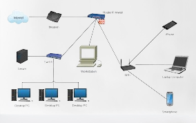
A LAN diagram provides a quick visualized overview of the network topology, either physical or logical. Looking at the diagram makes it easy to identify the components and how they interact.
Shows Connections Between Devices
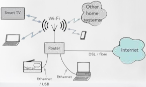
The diagram depicts how the different nodes such as PCs, printers, and servers connect to the internet. Lines are drawn between symbols representing the networked devices to indicate the links and flow of data.
Logical and Physical Topologies
LAN diagrams can represent the logical topology which focuses on device interconnections or the physical topology which shows the actual layout of the devices on the network.
Why Create a LAN Diagram?
There are several key reasons to create LAN network diagrams:
Understand Network Layout
A diagram provides an overview of the network layout and structure. It shows how all the parts fit together.
Identify Problems or Weaknesses
Visualizing the LAN helps identify any inefficiencies or weaknesses in the design that need to be addressed. Traffic bottlenecks or security risks may be spotted.
Plan Upgrades and Changes
Diagrams are useful references for planning future network upgrades and changes. The diagram can be modified to test out different configurations.
Elements of a LAN Diagram
LAN diagrams include three key elements:
Symbols for Devices
Standardized shapes represent different devices on the network like routers, switches, firewalls, servers, PCs, printers etc. Unique icons help identify device types.
Lines Showing Connections
Lines link the device symbols to depict the physical or logical connections between them. Different line styles indicate wired or wireless links.
Labels for Devices and Connections
Each device and link line should be clearly labeled with names or IP addresses to identify the connections.
Types of LAN Diagrams
There are three basic types of LAN network diagrams:
Logical Diagram
Shows how devices interact but not their physical locations. Focuses on the topology like star, bus, ring, and mesh.
Physical Diagram
Shows the actual office layout and device positions connected by cables. Helps plan wiring and placements.
Geographic Diagram
For large networks crossing multiple locations. Depicts devices, links between sites, WAN connections, etc.
Tips for Creating LAN Diagrams
Follow these tips for clear and effective LAN network diagrams:

Use Standard Symbols
Use universally recognized shapes for routers, switches, firewalls, workstations, etc. This makes the diagram more understandable.
Keep It Simple
Don’t overload the diagram. Only relevant devices and connections need to be shown. Too much detail obscures the key information.
Show Key Details Only
Focus on showing the most important devices, nodes, and links rather than every nitty-gritty technical element.
Use Legends and Labels
Provide legends to explain what the symbols mean. Label devices and links clearly for easy understanding.
LAN Diagram Tools
Popular software tools to easily create LAN diagrams include:
Microsoft Visio
Widely used for network diagrams with abundant templates, shapes, and tools. Easy to learn and use.
Lucidchart
Web-based program with drag-and-drop shapes to design diagrams online for collaboration.
SmartDraw
User-friendly app with an intuitive interface to quickly build network diagrams for businesses.
Conclusion
LAN network diagrams provide an easy to comprehend visual map of the local area network structure and connectivity. They help understand and troubleshoot complex networks and are an essential tool for installers, IT administrators, and managers.
Standardized shapes and labels along with a clean layout make diagrams meaningful. There are many powerful software tools available to efficiently create detailed and professional-looking LAN diagrams.
FAQs
What is the main benefit of a LAN diagram?
The main benefit is it provides an easy-to-understand visual reference for the network topology and connections between devices.
What basic elements should a LAN diagram contain?
It should contain device symbols, connecting lines showing data flow, and text labels naming the devices and connections.
What software can be used to draw a LAN diagram?
Popular options are Microsoft Visio, Lucidchart, and SmartDraw which provide templates and tools to create network diagrams.
Should wireless connections be shown differently than wired?
Yes, it is common to represent wireless connections with dotted or dashed lines compared to solid lines for wired.
Is it necessary to show every single device and link?
No, it’s best to simplify the diagram and show only key devices, connections, and layouts relevant to the focus.